SCIENCE WORK SHOP
About hobby electronics and scince ideas
Wednesday, February 22, 2012
Wednesday, October 5, 2011
Video transmitter
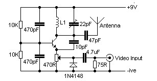
Video transmitterHere's a simple video transmitter for VHF TV channel will accept baseband video input, hence it can be driven by most CCD cameras and VCR video outputs. It ouputs roughly 80mW and when used with a 40cm telescopic antenna over 100 metres range is possible.
[One Transistor Video Transmitter Schematic]
The transistor of the video transmitter can be a BC108, BC546, BC337 or a 2N2222. L1 is wound on a 10 mm air former. Use 6 turns 24 SWG for frequency 60-80 MHz, 4 turns for 150-180 MHz, and 2 turns for 180-200 MHz
You can use this with a monochrome or color video signal. To transmit sound just build the wide band FM transmitter and tune it to the audio channel.
Thursday, April 28, 2011
Burning currency trick
This is a neat 'magic trick' that illustrates the process of combustion, the flammability of alcohol, and the special qualities of the material used to make currency.
Scientific Concept behind Burning Money
A combustion reaction occurs between alcohol and oxygen, producing heat and light (energy) and carbon dioxide and water.
C2H5OH + 4 O2 -> 2 CO2 + 3 H2O + energy
When the bill is soaked an alcohol-water solution, the alcohol has a high vapor pressure and is mainly on the outside of the material (a bill is more like fabric than paper, which is nice, if you've ever accidentally washed one). When the bill is lit, the alcohol is what actually burns. The temperature at which the alcohol burns is not high enough to evaporate the water, which has a high specific heat, so the bill remains wet and isn't able to catch fire on its own. After the alcohol has burned, the flame goes out, leaving a slightly damp dollar bill. Now you can perfome it in front of you friends
Theft preventer alarm
This circuit utilising a 555 timer IC can be used as an alarm system to prevent the theft of your luggage, burglars breaking into your house etc. The alarms goes ON when a thin wire, usually as thin as a hair is broken.
The circuit is straightforward. It uses a 555 IC wired as an astable multivibrator to produce a tone of frequency of about 1kHz which gives out a shrill noise to scare away the burglar.
The wire used to set off the alarm can be made of a thin copper wire like SWG 36 or higher.
You can even use single strands of copper form a power cable. The circuit operates on a wide range of voltages from 5V to 15V.
The speaker and the circuit could be housed inside a tin can with holes drilled on the speaker side for the sound to come out.
Component List :-
1) 9 Volt Power Source
2) Speaker
3) IC NE555
4) Resistance 68K ohms, 10K ohms,1K ohms
5) Capacitor 0.01 Mfd -2pieces
6) Capacitor 1Mfd/15V
Ir Based Audio Transmitter
Now you can transmit the sound signal via IR,Made it with a few components
Component List:-
1) Laser diode (you can take it from a simple laser torch without removing lens)
2) Transistor 2N3904 or equivalent
3) Transistor 2N3906 or equivalent
4) Transistor 2N2222 or equivalent
5) Transistor BPW 17N or (can use LDR, but it will effect on the light)
6) Resistance 10K ohms- 4 pieces
7) Capacitor 0.1 Mf- 2pieces
8) Speaker
Wednesday, April 27, 2011
Fire Alarm
This is a simple circuit and it can be made easily.You can use starters using in tube lights.It can be easily collect from a electric shop.To adjust the sensor you want to brake up the cover of the starter and the glass without effecting the inner metal sheet.please adjust the metal sheet close.Wire the circuit.Put the battery,place the sensor towards the fire,you can hear a music from the speaker
Component List :-
1) 3 Volt Power Source
2) Speaker
3) Transistor 548B, 558B
4) Resistance 220K ohms, 10K ohms
5) Capacitor 0.01 Mfd
Original image
..........................................................................................................................................................................
Rain alarm
Water is a conductor of electricity. When water is in contact with the probe then there is a flow of current which reaches to the base of Q1. Transistor Q1 is a NPN transistor which conducts. With the conduction of Q1 electron reaches to Q2 which is a PNP transistor .Q2 also conducts and current flows through the speaker. In a speaker there is inductive coil which causes motion in one direction and also produce induce current which is in opposite direction to the flow of current this induce current in the form of pulse flows through a capacitor, resistance and switches off Q1 and relax .this process repeats again and again till probe is in contact with water or we can say there is a oscillation in the circuit thus speaker diaphragm vibrates and gives a tone. Frequency of the circuit depends on the value of Speaker Coil impendence, Capacitor and Resistance Value.
Component List :-
1) 3 Volt Power Source
2) Speaker
3) Transistor 548B, 558B
4) Resistance 220K ohms, 10K ohms
5) Capacitor 0.01 Mfd
Original image
...................................................................................................................................................................
Subscribe to:
Comments (Atom)


